The most common non-standard. Welcome to this interactive flange bolting calculator from HYTORCThe program computes recommended torque values bolting patterns tool selection and pump pressure settings for.
2
It was probably introduced because the table 2-51.

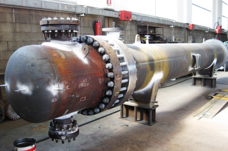
. Modulus of elasticity at design temp. Non standard flange Non-standard flanges will only be used in cases where pressure temperature and size requirements exceed the capabilities of standard flanges. Custom flange on standard nozzle is not currently possible possible enhancement.
Non ASME standard flange design. Pressure Relieving Devices Section II. Non-standard flanges are designed and calculated according to ASME VIII Div1 Appendix 2 and Appendix S and according to ASME VIII Div2 part 416.
The Flange design and calculation of ULMA Piping certified for by the API and ISO. Root diameter d b. Of bolts Fillet size 8 mm BCD C 650 2 x 8 2 2381 OD of flange A 725 2 x 2381 Width of gasket Gasket OD Gasket ID Minimum spacing of bolts 725 mm.
Note not a better. Weld Neck Raised Face. Select M20 x 24 No.
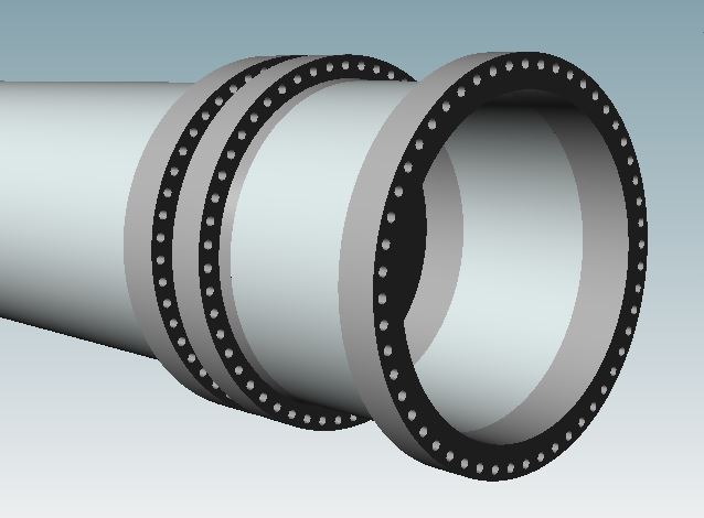
Contents CONTENTS AND STRUCTURE OF THE. Loose flange means that the flange is not directly fixed on the shell or fixed but can not guarantee that the flange in the shell as a whole to bear the bolt load structure. However a separate analysis for the non standard flange can be performed.
Modulus of elasticity at atmospheric temp. Number of bolts n-. Flanges imports Øᴳ N w and bₒ from this flange gaskets calculator.
Concept of program operation Four primary rules of program construction have been adopted. The first six options require the dimen- sions of the gasket like inner and outer diameter bolt hole size and length and width. At user-defined flanges the type of gasket has to be chosen.
Commercial program will take care of these including. Flange calc is complicate with many factors to play around including hub thickness at large endsmall end and hub length. For Non-Standard Flanges.
Provide a compressive force Wm2 which is needed to seat the gasket during initial assembly of the. You must however remember to save³ the gasket calculation prior to importing the output data into Flanges. Software construction supports the design and calculation process for all available standards.
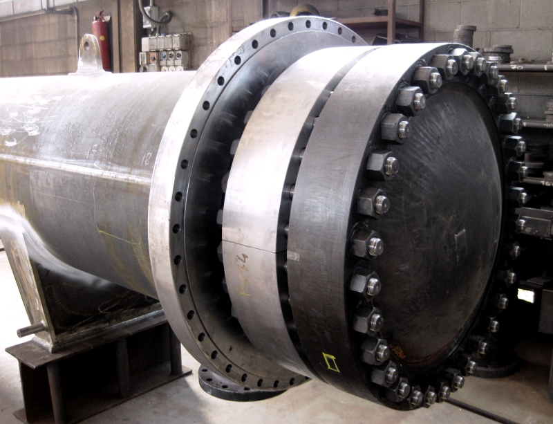
Removes any possible correlation between ASME flange calculation methods and flange manufacturers provided m and y values. These flanges have special characteristics requiring a specific design process to fit the working conditions of a specific application. Counter a pressure-induced force Wm1 which tends to pry open the flange in operation 2.
But often there is a requirement for designing non-circular flanges particularly ovalelliptical. ASME Flange Design Calculations. By Abdel Halim Galala in forum Engineering Spreadsheets Presentations.
ASME Flange Design Calculation ASME Flange Design Calculation Rating. Gasket OD 1775 Gasket. We have to proceed a design calculations as per ASME code Section VIII Division 1-Mandatory Appendix 2 Rules for Bolted Flange Connections with.
ASME Section VIII Division 1 Appendix 2 deals with the circular type flange design. Fully understand the design and calculation process for Non-Standard Flanges and at the same time identify the keys of a good design. 26 Description Flange qualified for B313 service per 30451 b using ASME BPVC Section VIII.

Jmse Free Full Text Structural Analysis And Experimental Study On The Spherical Seal Of A Subsea Connector Based On A Non Standard O Ring Seal Html

Flange Calculations According To En 1591 1 Youtube
What Will Be The Future Of The New Flange Calculation Methods Sant Ambrogio Servizi Industriali
Flange An Overview Sciencedirect Topics
What Will Be The Future Of The New Flange Calculation Methods Sant Ambrogio Servizi Industriali
What Will Be The Future Of The New Flange Calculation Methods Sant Ambrogio Servizi Industriali

Flange An Overview Sciencedirect Topics

Flange Gaskets Calculator Rtj Bx Rx Caf Calqlata
0 comments
Post a Comment